As solar farms get bigger and more powerful, flexible cables can help meet the demands of these large-scale operations.
By Sammy Germany
While creating a better power-management system at higher voltage levels, a solar power plant’s balance of system (BOS) requirements place extraordinary demands on power cables that conduct electricity from the prime mover to power-gathering systems. The ability to meet these demands affects the safe operation of these solar systems.
Power cables enable the flow of electricity from power conversion equipment (through step-up transformers) to the grid interconnection switchgear and load centers, which monitor and protect the entire system. Due to the cost of concrete solar equipment pads, conduit, power cables and equipment, it is critical to ensure all power systems are within proximity to enhance power quality and reduce the cost of large cable runs and terminations. In some cases, this will require using conductors that are flexible, multi-strain, very high power and efficient.
In above- and below-ground applications and restricted spaces, flexible diesel locomotive (DLO) cable is recommended for its flexibility and capacity for maximum applied voltages to the grid interconnection. DLO will still keep the flexibility of a smaller conductor in larger conductor configurations. Solar power farms are moving quickly from DC strings of 1,000 volts to those from 1,500 volts and higher for grid-tie interconnection. This trend of more power will require a perfect conductor and wire termination.
MATCHING CONNECTOR TO CABLE
Flexible-conductor cable (flex cable), like DLO, has become increasingly popular in the last few years for conducting solar-powered electricity. Flex cable is easier to maneuver in tight spaces — above or below grade — particularly with sizes beginning at 250 thousand circular mils (MCM), as well as when cable changes position frequently, as in underground applications.
There are many different flex cable classifications and strands, so it is important to match the termination to the proper conductor size or specification.
Regardless of whether connectors are manufactured for specific applications, or, like those from Thomas & Betts (T&B), are dual rated for both B- or C-Code and flex cable, they must be clearly identified for the proper application, as required by UL standards.
There is a wide variety of compression connectors that includes, for example, one- and two-hole lugs, butt splices and H-taps and C-taps. There also are connectors available for copper, aluminum or copper-clad aluminum conductors.
Compression connectors offer several advantages over mechanical connectors:
• When properly installed with the correct tooling, connections are permanent and cannot be loosened accidentally.
• Connections are irreversible, which is sometimes required for grounding applications.
• Low-profile crimps are easier to insulate.
• Some connectors are available with an oxide inhibitor.
The disadvantages are:
• Each conductor size requires its own connector.
• Crimp tooling is needed to make a properly calibrated connection.
CRIMPING STYLES OVERVIEW
Traditionally, there were two crimping methods for installing compression connectors: the indent-style crimp, made by compression tools without dies, or the hex-style crimp, made by compression tools equipped with interchangeable hex dies.

Indent-Style
Indent-Style Crimp
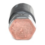
The indent-style crimp offers reliable electrical performance and approved, calibrated pullout resistance, as long as it is correctly done with a proper tool that corresponds to the size of cable and connector. An indent-style crimp leaves the connector with rounded edges and the capability to produce an arc flash. The strands are formed tightly together inside the connector, which eliminates virtually all air gaps from the conductor. One disadvantage of an indent-style crimp is that it does not provide for the inspection of a proper crimp.

Hex-Style
Hex-Style Crimp
The hex-style crimp has been the industry standard for crimping compression connectors onto B- and C-Code copper and aluminum/copper cables up to 1,000 MCM. The T&B Blackburn Color-Keyed system, for example, enables the installer to determine the proper die quickly, by matching the color code to the connector. The hex-style crimp results in superior electrical performance and calibrated pullout strength, while hex dies emboss the die code onto the connector for easy inspection and verification of a proper crimp after installation.

Hex-Flex
Hex-Flex Die System
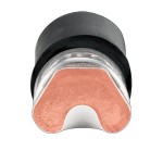
A third method of attaching connectors to flexible conductors was recently introduced. It combines the best of the indent- and hex-style crimp: superior calibrated pullout ratings and the ability to inspect for a proper QA/QC measured and documented crimp. The T&B Hex-Flex Die System combines standard Color-Keyed hex die halves for color-coding and die embossing for easy identification and inspection, with an indenter, which is round and smooth, and produces the higher pullout values across all types of flex cables. The higher pullout values created also reduce the number of crimps required on most connectors.
[source: http://www.solarbuildermag.com/featured/secure-connections/]
Leave a Reply
You must be logged in to post a comment.