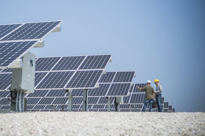
Everyone knows that starting with a solid foundation is a baseline for reliability—no matter what you’re building, installing or commissioning. A reliable baseline in photovoltaic (PV) systems is important for longevity of the equipment, safety, return on investment and warranties—among others. Here is what you need to know to get started off on the right foot with your next PV system install.
Calculate expected system production
How much your system will produce is based on the solar resource available, considering shading and other factors. Solar resource is measured in peak sun hours—the number of hours you receive 1,000 watts per square meter per day. To determine the actual solar irradiance (watts/m2) and shading, you can use an irradiance meter such as the Amprobe SOLAR-100—this will be your baseline.
Example: You have a 10 kW PV array in an area with a solar resource of 6,000 watts per square meter, or 6 peak sun hours. Calculate the expected annual production by multiplying the 10-kW array x 6 peak sun hours x 365 days per year x 0.85 (15% derating due to power losses in wiring and inverter). This array should produce 18,615 kWh of energy per year, or 51 kWh per day.
Solar installer webinar this week: Tips to reduce truck rolls, better monitor your solar fleet
Verify array installation against design
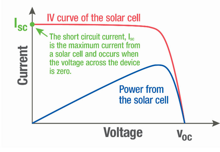
The performance of a PV array can be determined by its current-voltage (IV) curve. Inverters do more than convert DC to AC. They maximize their power output by capturing the current and voltage. Since power is voltage x current, this is the point at which the string is producing the most power.
• Short circuit current (Isc): the maximum current from a cell and no power will be produced because there is no voltage difference—the positive and negative wires are touching.
• Open circuit voltage (Voc): the maximum voltage from a cell and no power will be produced because the circuit is open.
• Maximum power point (mpp): the point at which the module produces the most power.
Once installed, you need to verify the system operates as designed. The verification process includes measuring electrical characteristics and actual power output of the array.
Step 1: Find the Isc and Voc using the module datasheet. Note that you will need to measure the Voc and Isc before and after installation.
Step 2: Determine the voltage between the positive and negative terminals. To do this, you will need to measure Voc using a clamp meter, such as a Fluke 381 Remote Display True RMS AC/DC Clamp Meter with iFlex.
Step 3: Determine the temperature of the module to account for the effect of temperature on Voc (the lower the temperature, the higher the voltage and vice versa. You can use a digital IR thermometer, such as the Fluke 64 MAX IR Thermometer to gather this information.
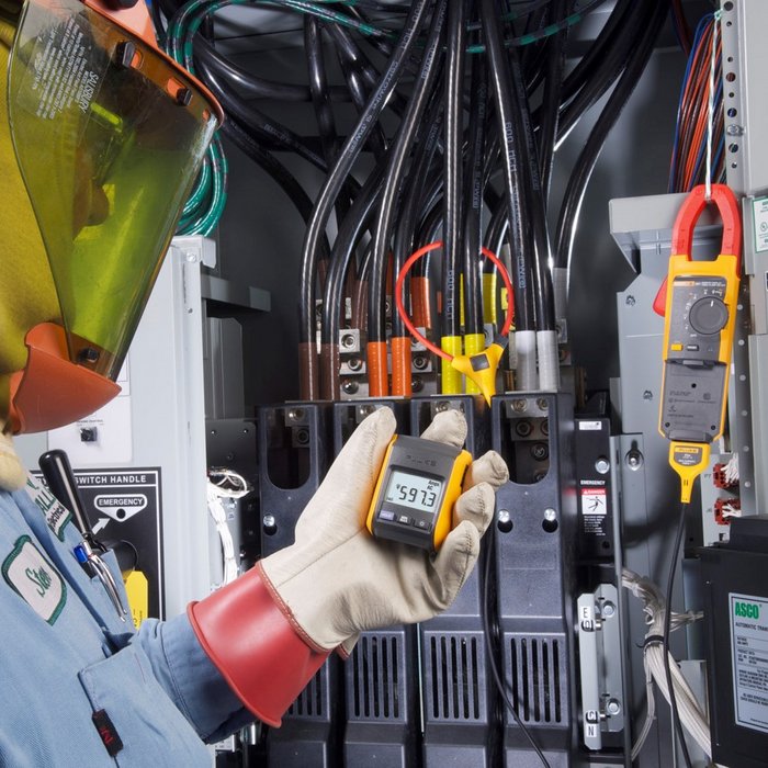
Fluke 381 clamp meter with remote display ©Rich Frishman
Step 4: Check the conductor polarity while testing Voc. If it is reversed, it can mean that in the combiner box other circuits may be unintentionally connected in series, resulting in voltages over the maximum inverter input voltage.
Step 5: Disconnect all parallel circuits and safely short the circuit.
Step 6: Measure the current between the positive and negative terminals through a multimeter. Set the dial to a current greater than expected. Record the values of Isc and Voc.
Step 7: Use your system’s computer interface to read the actual power output of the array.
Step 8: Check the insulation resistance of your conductors, the connections between modules and between modules and racking, and your resistance to ground. Use the Fluke 1625-2 GEO Earth Ground Tester to measure earth ground resistance to ensure a resistance of less than 5 ohms.
Specifying electrical characteristics of modules
Even when installed correctly, a PV system may not produce as expected. It is very important to specify the electrical characteristics for a module because inverters have minimum and maximum input currents, below and above which they will not output any power.
One scenario you might come across is an open circuit voltage or short circuit current that is higher or lower than on the datasheet. This means that your string has a module(s) with characteristics that are not to specification. The inverter may not output power if the open circuit voltage is out of range and you may have a module mismatch if the short circuit current is out of range. The latter can severely degrade your array’s performance because the current of a string is limited by the module with the lowest current.
If you come across this scenario, identify and replace the modules.
Troubleshooting low power output
A lower-than-expected power output could be a sign that you have a problem. Fluctuating output is expected, but output that is consistently less than expected could be the result of one or more issues, including a faulty string, a ground fault, or shading.
Faulty string: The accumulation of current and heat on a short-circuited cell—known as hot spots—leads to reduced performance and fire. Use of a thermal imager can quickly (and safely) identify hot spots.
Ground faults: These are harder to diagnose. Each conductor, including the equipment grounding conductor (EGC) must be tested for voltage and current. Voltage and current on the EGC is an indication of a ground fault. Ground faults occur due to damaged conductor insulation, improper installation, pinched wires, and water, which can create an electrical connection between a conductor and the EGC. Find the source of the problem and replace the damaged wires or improve the conditions.

Shading: Low power output can be the result of environmental or design issues, such as shading, poor tilt, and compass direction (azimuth angle) for the location. Use a solar pathfinder to identify any new sources of shading—then remove, if possible. Changing the tilt and compass direction of the array may not be possible, but it is still important to know the tilt and azimuth angles to establish a baseline for future reference.
Additional considerations when troubleshooting low power output include insulation resistance and batteries. Decreased insulation resistance is a common issue in large-scale PV systems where the power from a solar system goes through transformers after being inverted to step up the voltage, then to switchgear and medium voltage cables. For medium and high voltage cables, use the Fluke 1555 FC 10 kV Insulation Tester, which can test up to 10,000 volts. For systems with batteries, compare the expected battery voltage and state of charge with the actual using the Fluke 500 Series Battery Analyzer.
Sean Silvey is a product and application specialist for Fluke, which manufactures electrical test and measurement tools.
— Solar Builder magazine

Leave a Reply
You must be logged in to post a comment.