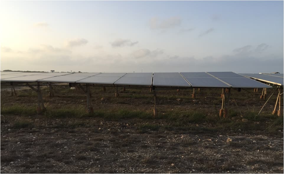
Photo: PV Diagnostics
One of the most important factors while optimizing the cost of a solar power plant is Module Mounting Structure (MMS), which is a key ingredient in the successful running of a solar power plant. Most of the BoS components like transformers, inverter, cables, SCB, etc. are bought from the suppliers but the designing of modules mounting structures has to be done by an EPC and can prove fatal for the power plant if not done properly.
The design of modules mounting structures are typically of three types based on technology:
1. Fixed tilt
2. Seasonal tilt
3. Trackers
The design strength of the module mounting structure depends largely on wind speed, soil type and location of the site. A PV plant is expected to last for at least 25 years and it is important for the module mounting structure to remain in satisfactory condition for the complete life of the project and bear the pressure of natural phenomena which are not prevalent but could happen during its lifetime. In our working experience, we came across many sites with severe structural defects which depleted the life of the plant considerably. These issues are compiled in association with Agami Engineering and are broadly classified into 2 categories:
1. Design/Installation issue
2. O&M issue
Design/Installation Issue
These issues are mainly because of faulty practices followed at the time of designing and installation of the solar plant. The reason may involve the ignorance of EPCs involved or wrong considerations taken during the designing level. Some of these issues are discussed below:
1. Variable structural tilt
At another site in Gujarat, there was evident intra and inter string variable structural tilt along with variable azimuth tilt. This resulted in one table causing the shadow on another table adjacent to it. Variation in tilt was as high as 4° in some of the adjacent tables. Consequently, these adjacent tables were receiving variable radiations differing by as high as 2%. It was estimated that the non-optimally tilted table would cause an average reduction of 1% in the radiation annually. Also, the tables receiving less radiation would be generating 1% lesser power than remaining tables. Similarly, variation in azimuth angle was as high as 3° in some of the adjacent tables which caused the radiation variation in the adjacent tables leading to mismatch loss.
 and Choice
In some tables, the impact could be higher due to variation in both tilt and azimuth. Apart from the generation loss, this will also cause accelerated degradation due to mismatch and higher temperature in affected tables.
2. Unstable structures
The strength of the structure is tested when there is high wind in the region. We have observed a high level of vibrations and noise around the tables at such times. The reason might be loose braces and/or unstable structures. Another possibility could be inaccurate assumptions of maximum wind speed or even ignorance of the fact that the region under consideration falls under the higher wind speed zones. These structures also had torsional stresses with changing azimuth angles.
3. Seasonal tilt specific issue
In seasonal tilt trackers, we have observed that the forward brace is found to be quite weak sometimes. Even under just the dead weight of the pv panels, it forms a “bow” with a close to 9-12 mm deflection at the center.

Photo: PV Diagnostics
4. Inappropriate tightening of clamps and nuts and bolts at cross bracing
This may not look as a big concern at the time of installation but if the clamps or nuts and bolts are not tightened properly they can cause some serious damage to the structure. We noticed this issue in one of the sites in Gujarat where clamps and nuts and bolts weren’t tightened properly at cross bracing as a result of which braces started coming out and weakened the support of the tables. Clamps also got loosened and came out.
5. Improper tightening of braces
On the same site, we observed another major fault. Due to improper tightening of braces, the whole table rotated on its axis and changed the tilt angle. As a result, there was high intra and inter row shading among adjacent tables leading to power loss. Shadow existed on the modules for more than 3 hours on a summer day which adversely affected the generation. It was estimated that around 10% of the tables might be facing this issue causing an estimated loss of about 1% in a year. This may also cause accelerated degradation in the shaded modules.
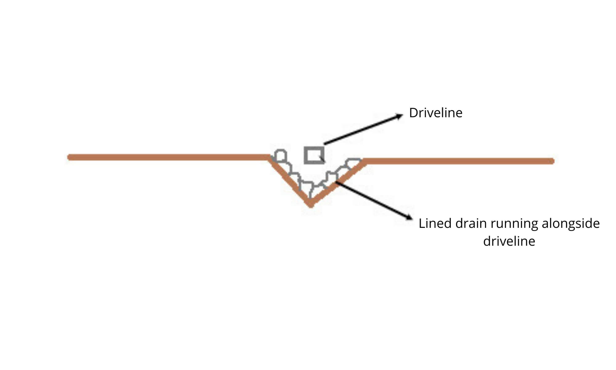
6. Less ground clearance for the driveline
We encountered this issue at a plant with trackers. The driveline drives the rotation in the torque tubes for all rows in one block or array. During the monsoon, flowing water and soil clogs beneath the driveline. When this happens, the trackers block’s movement is obstructed and might stop which can be observed via the actuator’s electrical signature. The O&M team then has to immediately mobilize and take necessary action, i.e. closing the actuator, clearing the blockage and digging some more around it as future insurance. To avoid this, permanent V-drain type structures can be created below all drivelines, lined with ‘rubble soling’ to maintain the shape.

Another difficulty observed because of this low driveline was that it connected to a low lying actuator which has risk of inundation for poorly draining soils like clays. V-drains were again suggested to handle this issue.
7. Driveline slip due to slotted joints
In the same location, the driveline was connected directly to the torque struts of all the rows as shown below via a “true” pin, which allows relative rotation between the strut and the driveline.
The driveline is supposed to act as a rigid member to rotate all the torque struts identically. Since, a single driveline is not possible for the entire array, the driveline is broken into segments and connected. Note that giving slots for this connection along the driveline is a major gamble. Slotted joints often slip and can result in improper operation of the whole tracker block. The motion of the driveline may not be translated correctly to the rotation of the subsequent torque struts. For this case, slotted bolts can be welded and a permanent connection can be created.

8. Badly formulated Purlin to Torque Tube connection.
Purlin should be rigidly connected to the torque tube such that the torque tube can achieve rigid rotation of the Purlins and eventually the panels. We observed that the connection was badly articulated and has resulted in tearing and enlargement of the purlin hole, thus resulting in a “wobble” of the purlin on the tube. This could prove catastrophic for the tracker, for any appreciable wind speed above 60 kmph as there will be galloping or flutter of the panels+purlins, similar to a flag on a post, thus causing irreparable damage to the PV module. Our suggestion was to fortify the connection using plates or appropriate stiffening items to resolve this issue.
O&M Issues
1. No scope of expansion to the modules
One of the unique issues was found in a plant in Rajasthan where the EPC did not provide scope for expansion to the modules. As a result, the frame of the modules started bulging because of excessive heat in the region. The moisture started penetrating within the modules and reduced insulation resistance because of which there were repeated cases of tripping of the inverters. The O&M team bypassed the GFDI to prevent the tripping of inverters instead of solving the problem of insulation resistance and module expansion. By-passing GFDI further led to excessive PID in the plant leading to power loss.
2. Construction of a site on the basin of a salt lake
On another site in Rajasthan located on the basin of a salt lake, we observed that the structures had high levels of corrosion driven by the highly corrosive nature of soil and hollow design of columns. Water collection inside the hollow columns further corroded the structure from inside. This can be rectified by repainting the structures with epoxy zinc coating to slow down the corrosion. The use of water for module cleaning provided moisture that accelerated the rate of corrosion and therefore we suggested reducing the water based cleaning frequency to once in a month. Apart from this, we also suggested cleaning of structures using low power air-blasts to remove salt and soil deposits. To overcome the problem of water logging, drain holes can be created at the bottom of the structure.
Webinar: Build Better Solar Structures with Integrated Project Delivery
Basic precautions to take:
1. Designing: At the time of designing, standards, wind zone, wind speed assumptions must be taken with consideration. Appropriate assumptions must be taken while simulations so you are able to draw beneficial conclusions from the results. Also, compatible BoM components like nut bolts, clamps, etc. should be selected during designing.
2. Installation: During installation, appropriate leveling and alignment should be done. Proper care must be taken while tightening of nut bolts and clamps and necessary investigations must be conducted while installation.
3. O&M: A regular inspection practice must be incorporated for corrosion, nuts and bolts strength and periodic tightening to ensure the reliability of module mounting structures.
Module Mounting Structures are the base of the plant and need expert surveillance. Therefore, all standardized and precautionary steps must be taken while designing, installing and operating the plant to make sure your plant stands upright for its economic life.
PV Diagnostics is a team of IIT Bombay graduates experts in diagnostics of solar power plants, quality control of modules for newly commissioned solar power plants and freshly procured modules. They provide end-to-end health check-up of solar power plants.
— Solar Builder magazine
Leave a Reply
You must be logged in to post a comment.