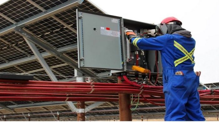
For those of us in the renewables industry, utility-scale solar projects have a particular look and feel. Row upon row of solar modules, PV stretching as far as the eye can see, perhaps drone capture from above that shows acres of gleaming panels. What you do not see are the underpinnings — aka balance of system (BOS) components — that are crucial to the development, energization and long-term energy yield of all solar power plants.
While it’s not the flashiest topic in the solar industry, cable management is a critical component. These bundles of cables underneath and next to the PV modules also represent hidden challenges that project engineers face on a daily basis. And it turns out that “cable geometry” or “cable math” is a misunderstood — but extremely important — facet of this industry.
To understand this, let’s look at the solar industry’s history.
Traditionally, engineers have relied on generalized tables provided by the National Electric Code (NEC) to determine cable ampacity, or how much power a cable can safely conduct over long periods of time. However, these tables do not account for the complexities of modern solar installations, particularly with innovative cable hangers and arrangements. As a result, engineers often make assumptions about cable capacities, leading to less-than-optimal cable ampacity selection.
One of the challenges that engineers face in determining cable ampacity is cable geometry, or orientation. In the past, engineers would organize cables into groupings called bundles, which were presumed to simplify design and reduce costs. However, bundling cables creates a problem that has been overlooked in the past: excessive heat.
The wires at utility-scale solar projects carry massive amounts of power — anywhere from several hundred kilowatts to a few megawatts — and therefore generate quite a bit of heat. By grouping wires together, the airflow is limited around each cable, which prevents natural heat dissipation. This increases the temperature in the cables and can accelerate the degradation of the insulation around the power cables, which can lead to decreased energy yield, premature wire burnout and other electrical failures.
To work around this problem, engineers discount the total power running through each cable based on recommendations from the NEC 310.15 table used today. It considers factors including cable type, ambient temperatures and bundle size to determine what amount of power a wire can handle safely.
The outcome of the math is simple: The bigger the bundle, the lower the airflow, the less energy allowed through a given cable. Often this results in a developer paying higher costs for larger cables to ensure the system will still be able to handle the power load once the cables have been bundled together.
The catch is that the NEC tables that engineers currently use to determine how much power to discount are not tailored to cable geometries that are frequently used in renewable energy. Without solar-specific tables, project engineers are left to approximate which pre-existing table is the best fit for a given situation. The key information missing from the existing code is a clear definition of what constitutes a cable bundle with more complex geometries.
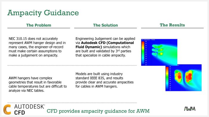
NEC 310.15 does not accurately represent modern hanger design. In fact, current NEC tables force engineers to assume almost all arrangements constitute a bundle, even those that allow significantly more cooling.
Up until now, developers have had no options for cable management systems that would increase energy yield and last through the lifetime of the power plant. New analysis from the Affordable Wire Management (AWM), NEI and Autodesk teams show a better option is on the horizon.
Enter cable geometry
Cable geometry, or smart “cable math,” is a new concept in cable management engineering that’s a game-changer.
The cable geometry concept is to design an optimal arrangement of wires that increases the total ampacity, or maximum current that can be run through a wire continuously without risk of degradation or failure. Cable geometry is complicated math that requires engineering expertise and a deep understanding of how convection and heat dissipation will affect nearby cables in different spacing patterns, and under different conditions.
This is where CFD (Computational Fluid Dynamic) analysis comes in handy. CFD analysis is an advanced modeling science that helps engineers understand how fluid movements, like convection cooling, function under different circumstances. It has been widely used by engineers in aviation and other industries for years.
Today, the AWM team utilizes Autodesk’s CFD software to solve the “hot” solar cable management problem. Let’s look at the analysis tables below:
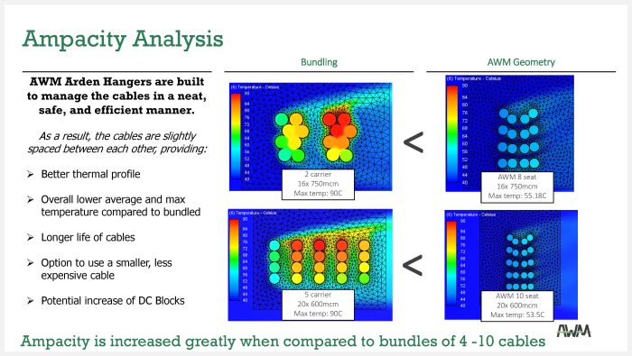
The visual output of the analysis, as shown above in the left diagram, illustrates the hotspots that occur in cable bundling. All the wires in the bundle are hot, and a few are near the maximum temperature indicated by red.
You might assume that spacing these cables out in just about any way would help, but the diagram shows this is not the case. When these cables are organized into parallel rows of four, shown on the bottom left, similar heat concentrations occur despite the apparent spacing. In this arrangement, multiple cables still reach dangerous temperatures. The right side diagrams show that if you re-engineer the design carefully and give those cables more room to breathe, those hotspots disappear.
By combining Autodesk’s computing expertise with AWM’s study on cable ampacity determination using CFD simulations, engineers can explore the effects of better airflow between cables, leading to improved system efficiency. Leveraging the power of CFD lets engineers simulate and analyze the heat transfer and airflow around cables in various hanger configurations, resulting in a more accurate assessment of cable ampacity. This innovative approach highlights the importance of considering the complexity and variability of cable arrangements in modern solar power plants.
AWM has found that CFD simulations can provide engineers with important guidance. For instance, Autodesk’s software has helped AWM optimize the Arden Series hanger design, our most recent hanger released, which in turn reduces costs for our customers. The CFD analysis provides the answer to that lingering question left by the existing NEC tables: “What do we need to consider a bundle of cable?”
This is an offering that truly solves real-world engineering challenges in the solar cable wire management sector.
The evidence is clear. Not all cable geometries are created equal, and now we have the tools to show why. With higher confidence in the cooling capabilities of a design, engineers can then downsize the cable size. This is significant, as smaller cables equal substantial cost savings – often in the millions of dollars for utility–scale solar projects — while increasing the operational safety and life of the cables.
In the long term, the creation of specialized NEC ampacity tables would allow for a widespread adoption of more efficient cable management solutions. We certainly hope that it becomes a reality in the near term.
For now, Autodesk’s CFD software analysis has started to fill in the information gap. Using this methodology, engineers and procurement teams can more accurately assess which cable management products will be most beneficial to their projects.
In fact, the application of the CFD analysis is starting to spark a change in how engineers think about and approach cable management altogether. Solar energy stakeholders can save on their bottom line, increase the lifespan of cables, and provide utility-scale asset owners with more certainty around ongoing project performance. All these factors can help bring the cost of solar down and speed the proliferation of clean power generation sources, which is vital to the future of our industry and planet.
Now, doesn’t that sound like an equation everyone can agree on? We think so.
Scott Rand is CEO and a founding member of Affordable Wire Management (AWM). AWM’s product line includes Arden Messenger Cable Hangers, Bonsai Module Hangers and the Solar LOTO lock-out offering. AWM’s solar cable management solutions are the preferred choice for top-ranked EPCs in North America. For more information, please email us at sales@affordablewm.com, or visit us on the web at: https://affordablewm.com/
Special thanks to Carson Bates of NEI for helping AWM refine the model and authoring our ampacity report.
Autodesk® CFD software creates computational fluid dynamics simulations that engineers and analysts use to intelligently predict how liquids and gases will perform. For more information, visit us on the web at: https://www.autodesk.com/products/cfd/overview
— Solar Builder magazine
Leave a Reply
You must be logged in to post a comment.