PEG’s low profile 8 degree tilt design produces between 217% and 241% more land yield (MWh/acre) compared to all trackers and fixed tilt solutions in the U.S.
A recent bankability report by DNV GL shows the value of PEG racking from Jurchen Technology for land constrained sites. In addition, with the release of a high snow load PEG solution, currently being installed in Austria, the PEG system may have the potential to prevent the termination many projects located in the North East USA as land suitable for solar becomes increasingly scarce. This is particularly true given the recent changes in the SMART Program for Massachusetts where land available for solar development was recently severely limited.
Before we get into those results, it helps to understand the uniqueness of the PEG system and its intallation process.
The PEG Installation Process
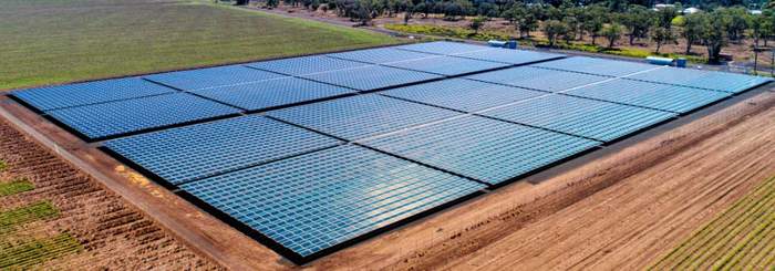
The PEG system, an endless sea of modules with narrow walking paths between the blocks.
Photo credit: Meralli Projects
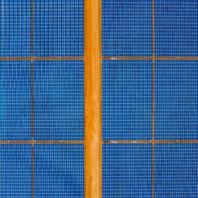
The PEG system’s installation takes place at ground level. Rods are rammed into the ground to a depth of 2 feet to 2.6 ft underground without concrete. DC cables are all above ground, and those system characteristics together with the system’s light weight eliminate the need for heavy machinery during the DC installation. The ramming process is done with electrohydraulic hammer. The PEG system cable management, running along the north edge of the block to allow shading of the cables and avoid shading caused by the combiner boxes.

DNV GL Bankability Report
The PEG’s main advantage according to the DNV GL report is in the efficiency of land use (the energy output per acre) and CAPEX reduction. The area-related energy harvest per acre is almost the same for either the fixed-tilt or single-axis trackers systems, while the PEG system exhibits a comparative 227% advantage over either of these types.
The photo at the top of this post shows an ocean of solar panels made possible with the PEG’s low profile 8 degree tilt design, which produces between 217% and 241% more land yield (MWh/acre) compared to all trackers and fixed tilt solutions in the U.S. The PEG ground coverage ratio is 3 times higher than single axis trackers and 2 times higher than fixed tilt. The PEG can produce 0.74 MW DC with 420 watt modules. These claims are independently verified by DNV GL in the PEG’s recently released bankability report released in June. (The PEG product has been installed in the field since 2014 and Jurchen has not received any warranty claims to date.)
Below you can see a table from the DNV GL bankability report highlighting 6 systems in 6 locations worldwide. The land yield of the PEG is ~220-240% higher compared to FT and SAT in all locations outside the tropics. The land yield is lower in the tropics though still higher vs both FT and SAT.

Also noted in the report is the PEG’s yield variance to trackers and fixed tilt systems. Given the 8 degree tilt of the system it is expected that there will be a decrease in yield. However, based on experience and as noted in the bankability report, there are significant CAPEX savings due to the simplistic design of the PEG. Many EPCs have experienced CAPEX savings that make up for the deceased yield to allow an attractive project returns and LCOE, however this is often difficult to determine without firsthand experience. LCOE analysis should be done on a project to project basis.

PEG System CAPEX Savings Highlights:
The PEG’s design simplicity and lightweight substructure are the system’s key characteristics. The steel bars and plates are made of hot-tip galvanized steel bars with ground and top plates, on which the PV modules are installed.
• Budget Overrun Risks – With no foundations, concrete, DC trenching and heavy machinery, and with minimized labor usage, and lightweight substructure, there are far less cost overrun risks compared to the installation of other substructures.
• Labor Efficiency – The installation process is highly streamlined minimizing the amount of labor needed to install the DC system to approximately 800 man hours per MWp with 380 watt modules. This positions the PEG as a strong candidate for unionized or high cost labor markets. Given the simplicity of the mechanical install low the use of skill labor is another contributor for the CAPEX saving.
• Material Costs – No concrete nor foundations are required,. Due to the high land utilization far less DC cabling is required.
• Health and Safety of Employees – The highest point of the PEG is about 1 meter or 2.5 feet. This avoids the risk of overhead injuries. The heaviest piece of material is 3 kg or 6.6. pounds. No heavy machinery is needed on site.
• Mobilization – Logistics is about 50% lower due to being able to fit 1.7 MW into a 40 foot container, assuming 380 watt panels. Additional savings is available since no heavy machinery is required.
High Snow Load Solution
The design for higher snow load, includes an additional 2 rods/plates underneath the modules, allowing 6 rods supporting each module. The additional two rods are located underneath the middle of the module’s long edges without the use of clamps, meaning the module just sits on the plates to mitigate the higher snow load. This solution is currently approved for snow loads up to 45 PSF and is shown below.
The standard PEG design is capable of handling snow loads up to 25 PSF. For snow loads of 30 PSF the top plates should be made of a stronger material.
— Solar Builder magazine

Leave a Reply
You must be logged in to post a comment.