
Module level power electronics (MLPE) are common in PV systems these days, and there are a few specific code sections concerning the voltage and current values of these systems. On this edition of Mayfield Renewables’ Code Corner, CEO Ryan Mayfield gives a great overview.
Applicable code sections explained in this short video include NEC 2020 690.7 (B)(2), 690.8 (A)(1)(d), and 690.8(A)(1)(e).
Definitions
The MLPE in this section include:
- dc to dc converters: A device that can provide an output dc voltage and current at a higher or lower value than the input dc voltage and current. A broad definition – “doesn’t really matter if it’s an optimizer or if it’s a rapid shutdown device, the requirements are really going to be just about the same in terms of voltage and current values,” Mayfield notes.
- Inverters. Equipment that converts dc to ac. So: microinverters.
690.7 (B)(2)
This section is specifically about the voltage output for dc to dc converters.
“In order to figure out what the maximum system voltage is, this is going to be a little different than our old systems where we would just take PV modules and string them together,” Mayfield says. “In this case, we are looking at the spec sheets for the dc to dc converters, and sometimes we also have to look at the connected inverter.”
To understand what the maximum system voltage is, we need to look at the system as a whole. How are they working together? Mayfield walks through an example:
“We have a very specific type of system, a SolarEdge system, where we have a specific dc to dc converter. It has to match up with a specific inverter. That’s a system that they work together. This is telling us that the maximum system voltage for this specific system for these specific inverters is 1,000 V.
Now if you’re using a dc to dc converter that is only going to be doing rapid shutdown functions, for example, the voltage just passes through, and so you have to look at the instructions in the manual and understand how that system acts … and use that to determine what your maximum system voltage is.”
690.8 (A)(1)(d)
This section covers the output current values for dc to dc converters, which is crucial for sizing circuits, figuring out overcurrent protection and the size of conductors.
“The maximum output circuit current is going to be whatever the dc to dc converter says that it is. What this means is that we have PV modules connected to our dc to dc converters,’ Mayfield says. “Those converters are listed by UL 1741, and the output current that is coming out of the dc to dc converters, there’s a limit to it. It can only put out so much. Your dc to dc converter manufacturer is going to say output current is 15 amps, 18 amps — whatever that value is. That number is that maximum value. Doesn’t really matter what is coming in on the input side. You could have a higher current coming in on the input side, the output is going to be regulated by the converter.”
On the flip side …
“This is kind of an extreme example, but let’s say you have a 5 amp input and the dc to dc converter says it has a 15 amp output. Sizing your conductors per code, you’re going to size it based on that 15 amp value.”
690.8 (A)(1)(e)
This covers the output of microinverters. Basically, you’re going to size this circuit exactly how you would a string inverter. And just like the dc to dc converters, the output current is regulated by the listing.
“So, if it says that it has a 15 amp maximum output, that’s all it can do,” Mayfield says. “It doesn’t matter what the input value is. You’re going to use that value as your basis of design for figuring out your current and your overcurrent protection and your conductor sizing.”
Previously on Code Corner…
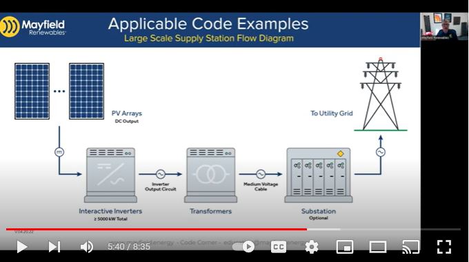
NEC 2020 | 691 | Large-scale PV electric supply stations
— Solar Builder magazine
[source: https://solarbuildermag.com/inverters/nec-2020-690-mlpe-voltage-and-current-values/]
Leave a Reply
You must be logged in to post a comment.