The National Electric Code allows for a few different ways to interconnect PV systems to utility systems. In two editions of Code Corner, Ryan Mayfield with Mayfield Renewables, explain busbar, load side interconnections in 705.12 (B)(3)(1) and (2), and then supply side connections in 705.11(C) and (D).
705.12 (B)(3)(1)
The sum of 125 percent of the power source(s) output circuit current and the rating of the overcurrent device protecting the busbar shall not exceed the ampacity of the busbar.
Mayfield: “We’re going to take the inverter output circuit, and we’re going to multiply it by 125 percent. That becomes the amount of current that the busbar will be subject to. We’re going to add that to the overcurrent device that’s protecting the busbar, and if those two don’t exceed the busbar rating, then you can put the solar output breaker wherever you want on that busbar.”
Example on that last point of being able to put the breaker anywhere you want, with this PV breaker located actually at the top of the busbar:
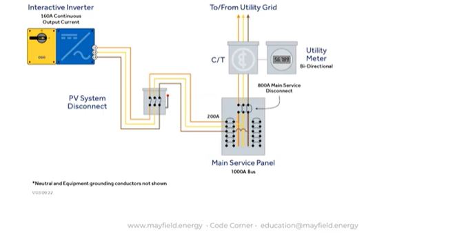
In this case, 160 amps x 125 = is 200 amps. “So, it’s not the rating of the breaker for the PV system, it’s a 125 percent times the continuous output current. That value plus the main service rating is what cannot exceed the busbar rating.”
705.12 (B)(3)(2)
Where two sources, one a primary power source and the other another power source, are located ar opposite ends of a busbar that contains loads, the sum of the 125 percent of the power-sources(s) output circuit current and the rating of the overcurrent device protecting the busbar shall not exceed 120 percent of the ampacity of the busbar. The busbar shall be sized for the loads connected in accordance with Article 220.
This is the “120 percent rule,” which is used a lot in the industry.
“The calculation is a little bit complicated, but basically the sum of the PV ac output amps times 125 percent plus the main breaker rating cannot be greater than 120 percent of the busbar,” Mayfield says. “If the math works out, you can go ahead and put your breaker at the opposite end of the busbar. If it doesn’t work out, you may be able to derate the main breaker to make the math work. You have to play with the numbers and see if you can do a load side connection.”
Note: There is a label that goes along with this: Warning: Power source output connection – do not relocate this overcurrent device.
In the case of the main, it’s the breaker rating. In the case of the inverter, it’s the output current times 125 percent.
Here’s an example. Contrast that with the example from (1).

“This is the classic residential application in the industry, really. You’re installing a PV system, the main service panel is 200 amps rated, and you’re putting an interactive inverter that has 32 amps of continuous output — 32 amps times 1.25 happens to be 40 amps exactly. What we’re saying here is that the sum of the continuous output current times 1.25, plus the breaker rating, cannot exceed 120 of the bus bar rating when those two are at the opposite end of the panel.”
Note the 40 amp breaker at the bottom of the panel.
“The idea here is there’s nowhere along that busbar that you’re going to have an overcurrent situation,” Mayfield clarifies. “In the case where solar’s doing great and pushing all that current back from the bottom of the panel, the current’s flowing up. If you happen to be running a bunch of loads at the exact same time, current from the utilities is coming down from the top feed in this case, and there’s nowhere that the 40 amps is additive to the 200 from the utility. You’re not at risk of having hot spots or too much current on your busbar. That’s really what we’re trying to avoid.”
If your math doesn’t work out and your inverter’s continuous output current is a little bit too high to make a load side connection, but you’re locked in and you don’t have the ability to do an easy supply side connection, you can consider derating the main breaker in the panel.
“Of course you have to get the client’s approval, and definitely look at the loads and make sure that that’s okay, but in a situation like this panel with a 200 amp, you could possibly derate it down to a 175 and create some more headroom there for you to actually make the math work out and be able to put a breaker down there where that 40 amp breaker is at the bottom of the bus.”
705.11 (C) | Overcurrent Protection.
The power source output circuit conductors shall be protected from overcurrent in accordance with 705.30. If fuses are not integral with the disconnecting means, the disconnecting means shall be located on the service side of the fuses.
[…]
Where the power source output circuit conductors make their connection to the service inside a building, they shall be protected with one of the following methods:
1) With an overcurrent device located within 3 m (10 ft) of conductor length in dwelling unites and 5 m (16.5) in other than dwelling units from the point of connection to the service,
2) In other than a dwelling unit, with an overcurrent device located within 20m (71 ft) of conductor length from the point of connection to the service, provided that cable limiters installed in all ungrounded conductors are located within 5m (16.5 ft) of conductor length from the point of connection to the service.
Note: In that missing portion, the code gets into what’s required when the service connections are made outside the building. Here we just focus on inside connections.
A question commonly asked from previous versions of NEC: Once I make a supply side connection, how far do I get to go before I need to have that overcurrent device?
“It was a little bit vague in previous code versions,” Mayfield notes. “What we have now is some definitive language. ‘You can have an overcurrent device located within 10 feet of conductor length’ — and that’s a big phrase right there, the conductor length – ‘and up to 16.5 ft in other than dwelling units.’
“How much conductor do we get by the time you make all the turns, all the connections, you’re going to be significantly less than 10 feet in physical distance between that disconnect and the point of connection. So, it becomes important that you have that room to mount that equipment inside buildings.”
Example:

Here’s how it looks on a non-dwelling three-phase application without cable limiters:

“We’re making connections on the service side, and there’s no overcurrent protection on the utility side, so we need to make sure that we’re protecting these conductors in the case of a fault, and we don’t have long lengths of conductors that are unprotected.”
The No. 2 option in this code, involving cable limiters, is not the most widely used, but it is available if needed (but only in C&I, not residential).
“Cable limiters are something you would install right at the at the point of connection and they’re a special device that helps protect the conductors. These are not the most straightforward things to always install. They can be big, they can be heavy, and so it becomes both an electrical and structural issue, and making sure that you have enough room inside the panel.”
705.11 (D) | Connections.
The connection of power source output circuit conductors to the service conductors shall be made using listed connectors as described in 110.14 and comply with all enclosure fill requirements. Any modifications to existing equipment shall be made in accordance with the manufacturer’s instructions or the modification must be evaluated for the application and have a field label applied. For meter socket enclosures or other equipment under exclusive control of the electric utility, only connections approved by the electric utility shall be permitted.
Note 1: This removes confusion from previous versions of NEC, in that the connectors used must be “as described in 110.14.”
“They need to be listed for the application, and they need to be service rated,” Mayfield says. “So it’s important that you’re looking at those connections, how are you making those connections, what are the actual physical components you’re connecting to? Do they have the right ratings per 110.14?”
Note 2: Modifications to existing equipment must be done per manufacturer’s instructions — “that’s kind of a given throughout code but it’s very clearly called out here.” Or, the other option is the modification must be evaluated for the application and field labeled.
“So, if you can’t get a manufacturer to say here’s how you do it then you’re going to have to get it field labeled,” Mayfield says. “And there are options for doing that on larger systems … and there’s also other options of getting manufacturers to supply that information on how to make those connections.”
More from NEC 2020
NEC 2020 | 690 | MLPE voltage and current values
NEC 2020 | 691 | Large-scale PV electric supply stations
— Solar Builder magazine
[source: https://solarbuildermag.com/news/nec-2020-705-11-load-and-supply-side-connections/]
Leave a Reply
You must be logged in to post a comment.